It seems like, of everyday electronic phenomena, one of those with the largest variation by temperature is the reverse leakage in semiconductor diodes. As explained in the note on thermistors, the resistivity of copper changes by about 3900 ppm/K, which is the basis of low-temperature “resistance temperature detectors”, and tungsten’s by about 4500 (though not consistently; it has phase changes). Carbon film resistors have a usually negative poorly controlled temperature coefficient of resistance; Panasonic, for example, spec their ERDS1, ERDS2, and ERDS25 carbon-film resistors at -150–-1000 ppm/K.
NP0/C0G ceramic capacitors are specified to change their capacitance
by under 1% over their temperature range and by under 30 ppm/K, while
film capacitors are typically ±200–650 ppm/K, depending on material
and humidity. (Thermocouples can in theory be arbitrarily precise but
they measure a temperature difference, and they tend to drift.)
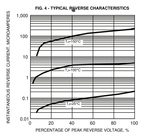
But feast your eyes on this plot of reverse leakage from General Semiconductor’s datasheet for 1N4001/4/7 diodes:
Over the 125° temperature range plotted here, they’re claiming the diode’s reverse leakage varies by a factor of 500–1500, depending on the voltage. That’s about 5–6% per degree, or to put it another way, 55000 ppm/K.
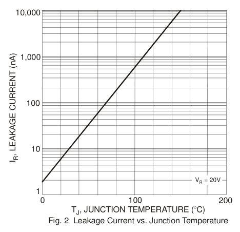
So if you can measure the current of the diode to within 1% while maintaining it at a relatively constant voltage, you can measure its temperature to within 200 mK. Silicon-junction signal diodes like the 1N4148 are qualitatively similar, but the currents are about an order of magnitude lower than the big rectum fryers; this plot from Diodes Inc.’s 1N4148 datasheet plots leakage versus temperature at a fixed voltage, rather than leakage versus voltage at various fixed temperatures:
And some other diodes are even better! Sunmate’s datasheet for their 1N5823 Schottkys, for example, also claims a typical reverse current ranging over three orders of magnitude, but over only 100°, amounting to over 7% of current variation per degree, and furthermore at low reverse voltages and more reasonable currents:
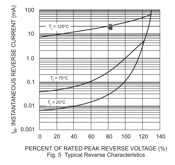
This diode is rated for 1500 pF typical capacitance at near-zero voltage, but a milliamp amounts to about 0.7 V/μs at that capacitance, so you’d need to be pretty quick to measure it discharging its own junction capacitance — you’d probably want to use some external capacitance, which might be at a different temperature.
By putting several such diodes in parallel you can increase the leakage current, which will help to make it easier to measure, and perhaps also average out some variation among them.
Typical ADCs can’t digitize a current, just a voltage, and the voltage is subject to a typically fairly large reference-voltage error (see Multimeter Metrology for lots on the difficulties of measuring voltages). To measure a current, you have to somehow convert it to a voltage. One way is to use a precise capacitor and measure the voltage change over time. But then you need to measure time.
With an ordinary crystal oscillator (“SPXO”) you ought to be able to measure the discharge rate with error of better than ±100 ppm over a standard -40°–+105° temperature range, or ±10 ppm if you temperature-compensate it.
Is that right? Digi-Key reports that their most-stocked crystal oscillator is the Abracon ABS05-32.768KHZ-9-T, which they sell for US$0.67–1.16, depending on quantity, from the 728,528 they have in stock. (Hopefully we can assume that it’s a relatively typical part due to being so popular.) It’s a surface-mount 32.768-kHz crystal, 1.6mm × 1.0mm × 0.5mm, whose error is specified as ±20 ppm at 25°, a temperature coefficient -0.02 to -0.04 “ppm/T²” with a “turn-over temperature” of 20°–30°, and aging of ±3 ppm in the first year if kept at 25° ±3°. If we assume that “ppm/T²” means ppm/K² for the squared difference of the temperature from the turnover point, where the frequency reaches its max, then at 10° or 40° we might have ΔT = 20K (if the turnover temperature is, respectively, 30° or 20°), thus 400K² and as much as 16 ppm reduction in frequency, or ±8 ppm over that temperature range, plus the ±20 ppm initial error and the ±3 ppm aging error, totaling ±31 ppm over that range, or ±11 ppm if we initially calibrate it. Of this ±11 ppm error, the thermal part reaches 1.6 ppm/K in the worst case at 10° or 40°, so if we can measure our temperature to within 2° we can compensate down to ±6 ppm. Much below that, we start running into tricky issues of things like thermal hysteresis.
To look at this another way, a 1° error in measuring the crystal’s temperature for thermal compensation, a 0.7% temperature error (7000 ppm), produces at worst a 1.6 ppm timing error in the +10°–+40° range.
This is maybe a little better than typical, but not that much. Another very popular crystal on Digi-Key is the 20.0000 MHz Citizen HCM4920000000ABJT (196,220 in stock) which is described as “±30 ppm”, but again that’s at 25°, plus another ±50 ppm over the -10°–+60° temperature range and ±5 ppm aging over the first year. They don’t specify the temperature coefficient, but if we figure that the frequency curve is, like the other crystal, parabolic with temperature with a maximum at 20°–30°, then that’s up to -100 ppm at a ΔT of 40K, so a worst-case “ppm/T²” of -0.0625 ppm/K².
So I think it’s reasonable to expect that we can get to ±10 ppm by calibrating and temperature-compensating random crystals, or ±1 ppm by calibrating and ovening them.
So, suppose the diode leakage current we’re measuring varies by 7% per degree, as the Schottky datasheet above shows it doing, and we’re timing how fast it discharges a capacitor. Looking more closely at Sunmate’s data sheet:
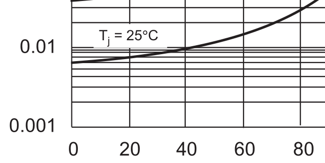
We can see that on the 25° curve it’s about 6 μA at 20% of rated peak reverse voltage and about 10 μA at 40%, which is to say, it’s nearly proportional to the voltage; below that, the leakage is nearly constant, and above, it starts to go superlinear. So if we take our discharge-time measurements with bias voltage near this point, errors in our reference voltage will mostly cancel out — the reverse leakage voltage is, locally, nearly ohmic. But errors in our timing won’t cancel out.
However, remember that a 1° error in temperature is an 0.7% error (7000 ppm), and it takes a 10% error in timing (100 000 ppm) to cause it. So the ±10 ppm timing error we expect, producing a ±10 ppm error in measuring the diode current, works out to a ±0.7 ppm temperature error, about 200 μK. So probably even an uncompensated SPXO with ±100 ppm would only add about 2 mK of error to the temperature measurement.
Properly characterizing the error introduced by an imprecise reference voltage is difficult without better information than the datasheet gives, but handwavingly I guess that a ±2% reference-voltage error around the ohmic voltage will produce a current measurement error of about 2% of ±2%, or ±400 ppm, producing about ±30 ppm temperature error, or 10 millikelvins.
Are there other things that would work better than a silicon Schottky diode?
I’ve already explored four-wire resistance temperature detectors, which have the advantage that their linear E–I relation permits measurements that precisely cancel out any non-drifting errors in the reference voltage, but have 15× smaller responses on an absolute scale.
The other temperature-measurement candidates that come to mind are LED reverse leakage (though apparently that’s typically very small and difficult to detect because the bandgap is larger, suggesting that maybe germanium diodes might work better if you can find one), ferroelectric-capacitor dielectric permittivity, and the aforementioned quartz crystal resonant frequency itself, this last not because it varies a lot but because it can be measured to greater precision. Most crystals, though, are cut to have their extremum in resonant frequency happen at 20°–30°, so it’s hard to measure them against each other, and we need to be far from the extremum to get a large effect.